Orbit-Q: MCU Card
STM32F405 MCU Card Development Platform - Specification, Pinout and Reference Guide
The STM32F405RGT6 is a mainstream high-performance microcontroller from STMicroelectronics built around the 32-bit ARM Cortex-M4 RISC core featuring a hardware Floating Point Unit (FPU) and full Digital Signal Processing (DSP) instruction sets. Operating at speeds up to 168 MHz and equipped with ST's Adaptive Real-Time (ART Accelerator), it executes instructions directly from Flash memory with zero wait states, delivering exceptional computational throughput for resource-constrained edge applications.
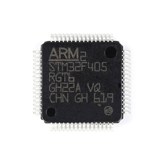
About STM32F405RGT6 Micro-Controller from ST Microelectronics
Key Technical Specifications
- Core Architecture: ARM 32-bit Cortex-M4 with FPU and DSP instructions
- Maximum Frequency: $168\,\text{MHz}$ (210 DMIPS / 1.25 DMIPS/MHz)
- Memory Configuration: $1\,\text{MB}$ of Flash memory and $192\,\text{KB}$ of SRAM (+ $4\,\text{KB}$ backup SRAM)
- Analog Peripherals: Two 12-bit ADCs (up to 24 channels) and two 12-bit DAC channels
- Connectivity & Interfaces: USB 2.0 OTG FS/HS, up to 3x I2C, 4x USARTs, 2x UARTs, 3x SPIs (with I2S audio support), 2x CAN interfaces, and SDIO
- Timers: Advanced-control motor-control timers, general-purpose 16-bit and 32-bit timers, and dual watchdog timers
Real-World Applications & Capabilities
- Drones & Flight Controllers: Widely deployed in high-performance multirotor flight control boards (such as Betaflight configurations) because its fast floating-point math efficiently handles high-speed sensor fusion and PID loop calculations.
- Advanced Robotics & Motor Control: Utilizes hardware-backed PWM timers and encoder interfaces to drive precise brushless DC (BLDC) motors, kinematic calculations, and real-time mechanical feedback loops.
- Industrial Automation: Powers programmable logic controllers (PLCs), multi-sensor data aggregators, and robust communication nodes leveraging industrial protocols like CAN bus.
- IoT & Modular Edge Devices: Delivers ample processing overhead for local data preprocessing, cryptographic communication stacks, and high-density modular carrier architectures.
- Edge AI & TinyML Capabilities (STM32Cube.AI): Beyond traditional control loops, the STM32F405RGT6 is fully equipped to execute lightweight machine learning and deep learning models at the edge using STM32Cube.AI. By leveraging the integrated ARM Cortex-M4 FPU and DSP instruction set, the microcontroller efficiently handles single-precision floating-point matrix multiplications, vector operations, and neural network inference layers.
- Practical AI Use Cases at the Edge:
- Predictive Maintenance: Running anomaly detection and vibration analysis directly on industrial motors or rotating machinery by processing high-frequency accelerometer data.
- Audio Classification & Keyword Spotting: Executing compact convolutional neural networks (CNNs) for localized speech recognition or acoustic event detection without relying on cloud connectivity.
- Sensor Fusion & Intelligent Filtering: Deploying tiny neural networks to clean noisy sensor inputs, perform gesture recognition, or adaptively tune control algorithms in real time.
Software Ecosystem & Development Environments
- Arduino IDE & PlatformIO: Fully supported via community and official STM32 core packages, allowing developers to build and upload projects using familiar Arduino libraries and frameworks.
- Professional IDEs: Compatible with STM32CubeIDE, Keil MDK, and IAR Embedded Workbench for advanced bare-metal, register-level, or FreeRTOS-based industrial development.
MicroPython Support & Advantages
The STM32F405 is MicroPython’s original target platform, launched alongside the official Pyboard in a 2013 Kickstarter campaign. Its hardware profile—featuring a 168 MHz ARM Cortex-M4 core, FPU, 1 MB Flash, and 192 KB SRAM—was specifically chosen as the ideal sweet spot for running a bare-metal Python interpreter. Consequently, the STM32 port serves as the project's foundational baseline, with peripheral drivers deeply optimized for this architecture. - Native MicroPython Execution: Runs lightweight Python 3 scripts directly on the bare metal, drastically accelerating the prototyping lifecycle without requiring C/C++ compilation for every iteration. - Performance Benefits for MicroPython: * Generous Memory Footprint: The 1 MB Flash memory provides ample storage for the MicroPython firmware image alongside user scripts, while the 192 KB SRAM easily handles interpreter runtime overhead and dynamic variable allocation. * Speed & Floating-Point Efficiency: The 168 MHz clock speed paired with the hardware Floating Point Unit (FPU) mitigates the performance penalty typically associated with interpreted languages, ensuring responsive script execution and efficient mathematical computations.
Drone & Flight Control Firmware Ecosystem
- Betaflight & INAV: Historically established as a powerhouse MCU for high-performance multirotor and fixed-wing flight controllers, efficiently executing high-frequency PID loops, gyro filtering, and real-time stabilization.
- ArduPilot: Capable of running advanced autonomous navigation routines, waypoint tracking, and complex multi-sensor fusion stacks for intelligent robotics.
The chip's blend of heavy crunching power, deterministic real-time behavior, and diverse peripheral integration makes it an industry standard for professional embedded engineering and rapid prototyping.
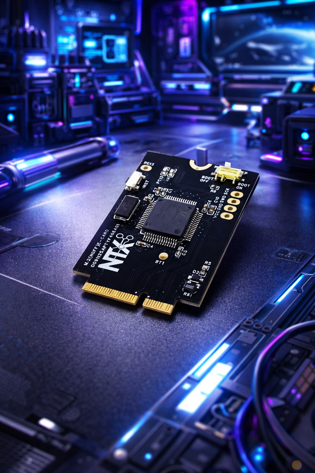
STM32F405RGT6 M.2 E-Card Hardware Specification
Overview
This documentation outlines the hardware specifications, layout features, and pin configuration for the NTX Systems custom STM32F405RGT6 M.2 E-Card (Part Number: D091125APTYF405A01). Built on an M.2 E-Key (NGFF) form factor, this compact module packs a high-performance ARM Cortex-M4 microcontroller into a standardized edge-connector design.
Core Specifications
- Microcontroller: STMicroelectronics STM32F405RGT6 (ARM Cortex-M4 32-bit RISC core with FPU)
- Operating Frequency: Up to 168 MHz
- Flash Memory: 1 MB
- SRAM: 192 KB (+ 4 KB backup SRAM)
- Clock Source: 8 MHz High-Speed External (HSE) crystal oscillator (Note: No OSC32 low-speed crystal installed)
- Operating Voltage: 3.3 V nominal input, regulated via onboard safety components
- Part Number:
D091125APTYF405A01
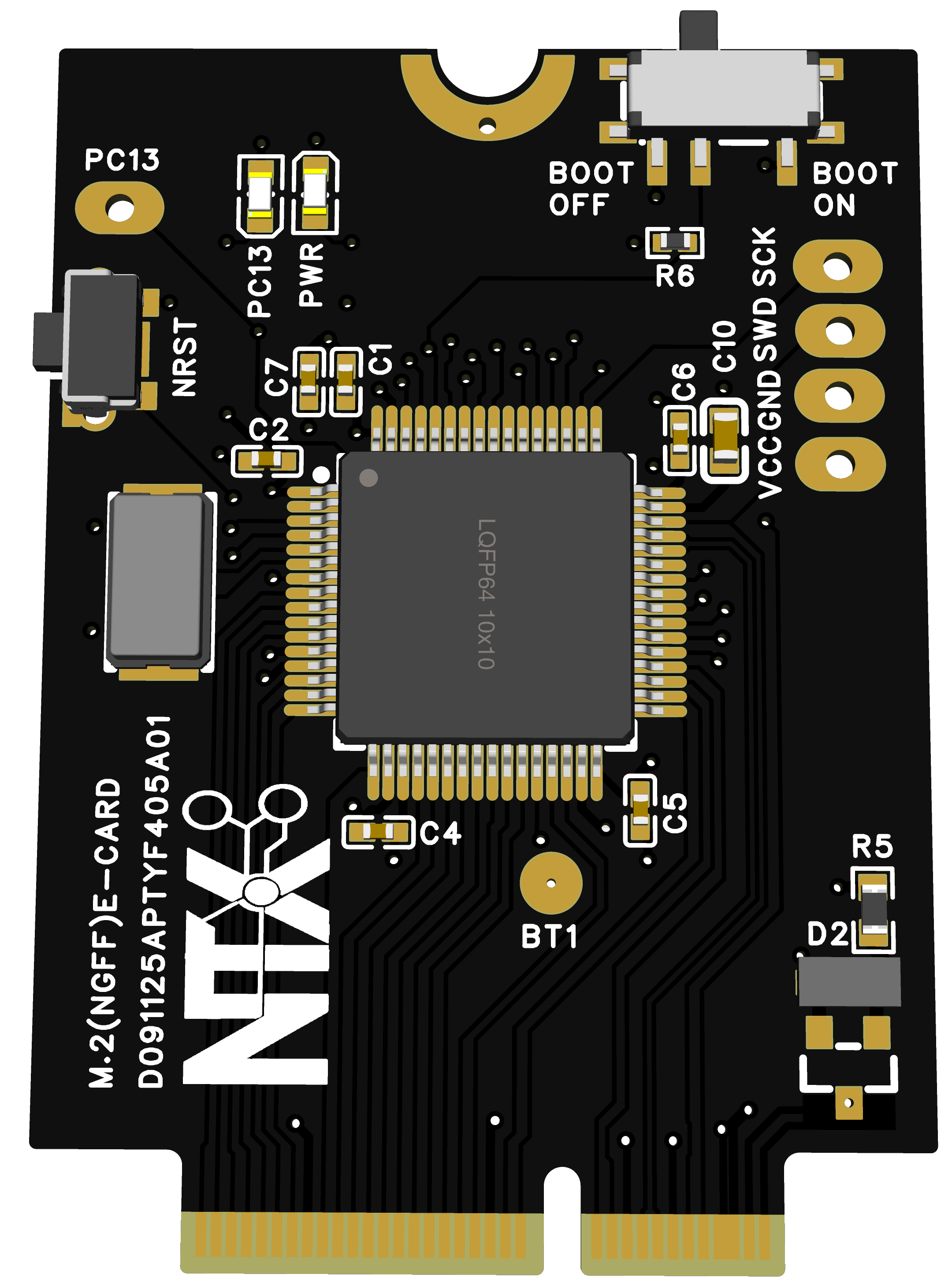
Power Management & Safety
- Reverse Polarity Protection: The 3.3 V power input line features an integrated hardware reverse polarity protection circuit to prevent damage from incorrect power supply connections.
- Power LED: An onboard power indicator LED wired directly to the 3.3 V rail indicates active power status
Onboard Controls & User Interface
- Reset Button (NRST): Tactile push-button switch connected to the microcontroller's hardware reset line.
- Boot Mode Selector: Onboard slide switch for configuring the
BOOT0pin state easily between operational modes (Boot OFF / Boot ON). - Status LED (PC13): Dedicated user/status LED connected to pin
PC13in an active-high configuration (LED lights up whenPC13goes HIGH).
Solder Pads & Extra Access Points
Because PC13 is utilized by the onboard status LED, it is omitted from the standard edge connector interface. However, dedicated test/solder pads are provided on the PCB for advanced access:
-
3V3 — Power rail access
-
GND — Ground reference
-
SWDIO — Serial Wire Debug Data
-
SWCLK — Serial Wire Debug Clock
-
BOOT1 — *BOOT1 configuration point
-
PC13 — Direct access pad for pin *PC13 (bypassing the basic interface)
1. Complete M.2 Pinout Mapping (Pins 1–68)
| Pin | Signal / Function | Pin | Signal / Function |
|---|---|---|---|
| 1 | VCC (3.3V / VIN) | 2 | VCC (3.3V / VIN) |
| 3 | GND | 4 | GND |
| 5 | PA14 (SWD / SWCLK) | 6 | PA13 (SWD / SWDIO) |
| 7 | GND | 8 | PA12 (USB-OTG / CAN1_TX) |
| 9 | PA11 (USB-OTG / CAN1_RX) | 10 | GND |
| 11 | PB15 (SPI2_MOSI) | 12 | PB14 (SPI2_MISO) |
| 13 | PB13 (SPI2_SCK) | 14 | PB12 (SPI2_NSS / CS) |
| 15 | GND | 16 | PB11 (I2C2_SDA / UART3_RX) |
| 17 | PB10 (I2C2_SCL / UART3_TX) | 18 | PB1 |
| 19 | PB0 | 20 | PC5 |
| 21 | PC4 | 22 | PA7 (SPI1_MOSI / TIM3_CH2) |
| 23 | PA6 (SPI1_MISO / TIM3_CH1) | 24 | PA5 (SPI1_SCK) |
| 25 | PA4 (SPI1_NSS / SD Card CS) | 26 | PA3 (USART2_RX) |
| 27 | GND | 28 | PA2 (USART2_TX) |
| 29 | PA1 (UART4_RX) | 30 | PA0 (UART4_TX / WKUP) |
| 31 | PC3 | 32 | PC2 |
| 33 | PC1 | 34 | PC0 |
| 35 | VCC | 36 | VCC |
| 37 | GND | 38 | GND |
| 39 | N.C. | 40 | N.C. |
| 41 | N.C. | 42 | N.C. |
| 43 | GND | 44 | PC6 (USART6_TX) |
| 45 | PC7 (USART6_RX) | 46 | PC8 |
| 47 | PC9 (I2C3_SDA) | 48 | N.C. |
| 49 | PC14 (OSC32_IN) | 50 | PC15 (OSC32_OUT) |
| 51 | PB9 | 52 | PB8 (TIM4_CH3) |
| 53 | BOOT0 | 54 | PB7 (I2C1_SDA / TIM4_CH2) |
| 55 | GND | 56 | PB6 (I2C1_SCL / TIM4_CH1) |
| 57 | PB5 | 58 | PB4 |
| 59 | PB3 (JTDO / TRACESWO) | 60 | PD2 (UART5_RX) |
| 61 | PC12 (SPI3_MOSI / UART5_TX) | 62 | PC11 (SPI3_MISO / UART3_RX) |
| 63 | PC10 (SPI3_SCK) | 64 | PA15 (SPI3_NSS) |
| 65 | PA10 (USART1_RX / TIM1_CH3) | 66 | PA9 (USART1_TX / TIM1_CH2) |
| 67 | GND | 68 | PA8 (I2C3_SCL / TIM1_CH1) |
2. Onboard Peripherals & Default Pin Mapping
- Onboard OLED Display (128 X 32, SSD1306):
- Protocol: I2C1 (
PB6= SCL,PB7= SDA) - I2C Address:
0x3C - Isolation Jumper: JP-2 (Bridge to connect MCU to display)
- Protocol: I2C1 (
- MicroSD Card Slot:
- Protocol: Hardware SPI1 (
PA4= CS,PA5= SCK,PA6= MISO,PA7= MOSI) - Isolation Jumper: JP-5
- Protocol: Hardware SPI1 (
- USB-to-UART Bridge (CP2102):
- Isolation Jumper: JP-3
- Onboard ST-LINK Debugger:
- Protocol: SWD (
PA13= SWDIO,PA14= SWCLK via Header A)
- Protocol: SWD (
3. STM32F405RGT6 MCU Pin Details
| Pin No. | Pin name after reset | Pin type | I/O structure | Alternate functions | Additional functions |
|---|---|---|---|---|---|
PC13 |
I/O | FT | EVENTOUT | RTC_AF1 | |
| 49 | PC14-OSC32_IN (PC14) |
I/O | FT | EVENTOUT | OSC32_IN(4) |
| 50 | PC15- OSC32_OUT (PC15) |
I/O | FT | EVENTOUT | OSC32_OUT |
| 34 | PC0 |
I/O | FT | OTG_HS_ULPI_STP/ EVENTOUT | ADC123_IN10 |
| 33 | PC1 |
I/O | FT | ETH_MDC/ EVENTOUT | ADC123_IN11 |
| 32 | PC2 |
I/O | FT | SPI2_MISO /OTG_HS_ULPI_DIR /TH_MII_TXD2/I2S2ext_SD/ EVENTOUT | ADC123_IN12 |
| 31 | PC3 |
I/O | FT | SPI2_MOSI / I2S2_SD / OTG_HS_ULPI_NXT / ETH_MII_TX_CLK/ EVENTOUT | ADC123_IN13 |
| 30 | PA0-WKUP (PA0) |
I/O | FT | USART2_CTS/ UART4_TX/ ETH_MII_CRS / TIM2_CH1_ETR/ TIM5_CH1 / TIM8_ETR/ EVENTOUT | ADC123_IN0/WKUP(4) |
| 29 | PA1 |
I/O | FT | USART2_RTS / UART4_RX/ ETH_RMII_REF_CLK / ETH_MII_RX_CLK / TIM5_CH2 / TIMM2_CH2/ EVENTOUT | ADC123_IN1 |
| 28 | PA2 |
I/O | FT | USART2_TX/TIM5_CH3 / TIM9_CH1 / TIM2_CH3 / ETH_MDIO/ EVENTOUT | ADC123_IN2 |
| 26 | PA3 |
I/O | FT | USART2_RX/TIM5_CH4 / TIM9_CH2 / TIM2_CH4 / OTG_HS_ULPI_D0 / ETH_MII_COL/ EVENTOUT | ADC123_IN3 |
| 25 | PA4 |
I/O | TC | SPI1_NSS / SPI3_NSS / USART2_CK / DCMI_HSYNC / OTG_HS_SOF/ I2S3_WS/ EVENTOUT | ADC12_IN4 /DAC1_OUT |
| 24 | PA5 |
I/O | TC | SPI1_SCK/ OTG_HS_ULPI_CK / TIM2_CH1_ETR/ TIM8_CHIN/ EVENTOUT | ADC12_IN5/ DAC2_OUT |
| 23 | PA6 |
I/O | FT | SPI1_MISO / TIM8_BKIN/TIM13_CH1 / DCMI_PIXCLK / TIM3_CH1 / TIM1_BKIN/ EVENTOUT | ADC12_IN6 |
| 22 | PA7 |
I/O | FT | SPI1_MOSI/ TIM8_CH1N / TIM14_CH1/TIM3_CH2/ ETH_MII_RX_DV / TIM1_CH1N / RMII_CRS_DV/ EVENTOUT | ADC12_IN7 |
| 21 | PC4 |
I/O | FT | ETH_RMII_RX_D0 / ETH_MII_RX_D0/ EVENTOUT | ADC12_IN14 |
| 20 | PC5 |
I/O | FT | ETH_RMII_RX_D1 / ETH_MII_RX_D1/ EVENTOUT | ADC12_IN15 |
| 19 | PB0 |
I/O | FT | TIM3_CH3 / TIM8_CH2N/ OTG_HS_ULPI_D1/ ETH_MII_RXD2 / TIM1_CH2N/ EVENTOUT | ADC12_IN8 |
| 18 | PB1 |
I/O | FT | TIM3_CH4 / TIM8_CH3N/ OTG_HS_ULPI_D2/ ETH_MII_RXD3 / TIM1_CH3N/ EVENTOUT | ADC12_IN9 |
| Solder Pad | PB2-BOOT1 (PB2) |
I/O | FT | EVENTOUT | - |
| 17 | PB10 |
I/O | FT | SPI2_SCK / I2S2_CK / I2C2_SCL/ USART3_TX / OTG_HS_ULPI_D3 / ETH_MII_RX_ER / TIM2_CH3/ EVENTOUT | - |
| 16 | PB11 |
I/O | FT | I2C2_SDA/USART3_RX/ OTG_HS_ULPI_D4 / ETH_RMII_TX_EN/ ETH_MII_TX_EN / TIM2_CH4/ EVENTOUT | - |
| 14 | PB12 |
I/O | FT | SPI2_NSS / I2S2_WS / I2C2_SMBA/ USART3_CK/ TIM1_BKIN / CAN2_RX / OTG_HS_ULPI_D5/ ETH_RMII_TXD0 / ETH_MII_TXD0/ OTG_HS_ID/ EVENTOUT | - |
| 13 | PB13 |
I/O | FT | SPI2_SCK / I2S2_CK / USART3_CTS/ TIM1_CH1N /CAN2_TX / OTG_HS_ULPI_D6 / ETH_RMII_TXD1 / ETH_MII_TXD1/ EVENTOUT | OTG_HS_VBUS |
| 12 | PB14 |
I/O | FT | SPI2_MISO/ TIM1_CH2N / TIM12_CH1 / OTG_HS_DM/ USART3_RTS / TIM8_CH2N/I2S2ext_SD/ EVENTOUT | - |
| 11 | PB15 |
I/O | FT | SPI2_MOSI / I2S2_SD/ TIM1_CH3N / TIM8_CH3N / TIM12_CH2 / OTG_HS_DP/ EVENTOUT | - |
| 44 | PC6 |
I/O | FT | I2S2_MCK / TIM8_CH1/SDIO_D6 / USART6_TX / DCMI_D0/TIM3_CH1/ EVENTOUT | - |
| 45 | PC7 |
I/O | FT | I2S3_MCK / TIM8_CH2/SDIO_D7 / USART6_RX / DCMI_D1/TIM3_CH2/ EVENTOUT | - |
| 46 | PC8 |
I/O | FT | TIM8_CH3/SDIO_D0 /TIM3_CH3/ USART6_CK / DCMI_D2/ EVENTOUT | - |
| 47 | PC9 |
I/O | FT | I2S_CKIN/ MCO2 / TIM8_CH4/SDIO_D1 / /I2C3_SDA / DCMI_D3 / TIM3_CH4/ EVENTOUT | - |
| 68 | PA8 |
I/O | FT | MCO1 / USART1_CK/ TIM1_CH1/ I2C3_SCL/ OTG_FS_SOF/ EVENTOUT | - |
| 66 | PA9 |
I/O | FT | USART1_TX/ TIM1_CH2 / I2C3_SMBA / DCMI_D0/ EVENTOUT | OTG_FS_VBUS |
| 65 | PA10 |
I/O | FT | USART1_RX/ TIM1_CH3/ OTG_FS_ID/DCMI_D1/ EVENTOUT | - |
| 9 | PA11 |
I/O | FT | USART1_CTS / CAN1_RX / TIM1_CH4 / OTG_FS_DM/ EVENTOUT | - |
| 8 | PA12 |
I/O | FT | USART1_RTS / CAN1_TX/ TIM1_ETR/ OTG_FS_DP/ EVENTOUT | - |
| 6 | PA13 (JTMS-SWDIO) |
I/O | FT | JTMS-SWDIO/ EVENTOUT | - |
| 5 | PA14 (JTCK-SWCLK) |
I/O | FT | JTCK-SWCLK/ EVENTOUT | - |
| 64 | PA15 (JTDI) |
I/O | FT | JTDI/ SPI3_NSS/ I2S3_WS/TIM2_CH1_ETR / SPI1_NSS / EVENTOUT | - |
| 63 | PC10 |
I/O | FT | SPI3_SCK / I2S3_CK/ UART4_TX/SDIO_D2 / DCMI_D8 / USART3_TX/ EVENTOUT | - |
| 62 | PC11 |
I/O | FT | UART4_RX/ SPI3_MISO / SDIO_D3 / DCMI_D4/USART3_RX / I2S3ext_SD/ EVENTOUT | - |
| 61 | PC12 |
I/O | FT | UART5_TX/SDIO_CK / DCMI_D9 / SPI3_MOSI /I2S3_SD / USART3_CK/ EVENTOUT | - |
| 60 | PD2 |
I/O | FT | TIM3_ETR/UART5_RX/ SDIO_CMD / DCMI_D11/ EVENTOUT | - |
| 59 | PB3 (JTDO/ TRACESWO) |
I/O | FT | JTDO/ TRACESWO/ SPI3_SCK / I2S3_CK / TIM2_CH2 / SPI1_SCK/ EVENTOUT | - |
| 58 | PB4 (NJTRST) |
I/O | FT | NJTRST/ SPI3_MISO / TIM3_CH1 / SPI1_MISO / I2S3ext_SD/ EVENTOUT | - |
| 57 | PB5 |
I/O | FT | I2C1_SMBA/ CAN2_RX / OTG_HS_ULPI_D7 / ETH_PPS_OUT/TIM3_CH 2 / SPI1_MOSI/ SPI3_MOSI / DCMI_D10 / I2S3_SD/ EVENTOUT | - |
| 56 | PB6 |
I/O | FT | I2C1_SCL/ TIM4_CH1 / CAN2_TX / DCMI_D5/USART1_TX/ EVENTOUT | - |
| 54 | PB7 |
I/O | FT | I2C1_SDA / FSMC_NL / DCMI_VSYNC / USART1_RX/ TIM4_CH2/ EVENTOUT | - |
| 53 | BOOT0 |
I | B | - | VPP |
| 52 | PB8 |
I/O | FT | TIM4_CH3/SDIO_D4/ TIM10_CH1 / DCMI_D6 / ETH_MII_TXD3 / I2C1_SCL/ CAN1_RX/ EVENTOUT | - |
| 51 | PB9 |
I/O | FT | SPI2_NSS/ I2S2_WS / TIM4_CH4/ TIM11_CH1/ SDIO_D5 / DCMI_D7 / I2C1_SDA / CAN1_TX/ EVENTOUT | - |
4. Arduino IDE Setup & Configuration
- Add Board Manager URL: Open Arduino IDE, go to File > Preferences, and paste the following URL into Additional board manager URLs: ```text https://github.com/stm32duino/BoardManagerFiles/raw/main/package_stmicroelectronics_index.json