ORBIT-Q
One Platform. Multiple MCU Possibilities.

Supported IDEs & Languages






Supported Microcontrollers









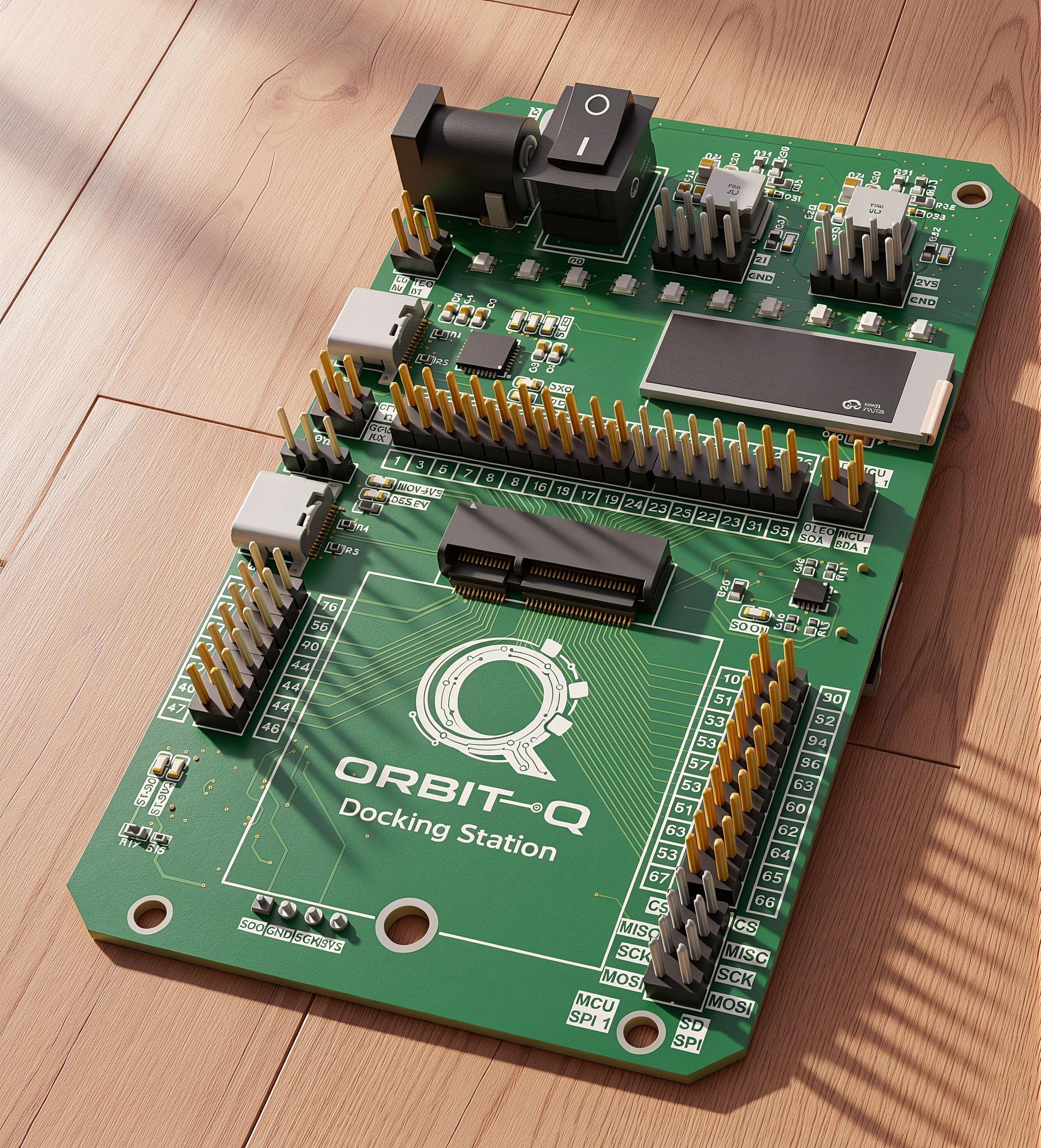
ORBIT-Q is a development board from NTX Systems Pvt. Ltd. that doesn't force you to start over every time your project changes. Instead of buying a new board for every new microcontroller, you just swap the card — the base unit stays the same, already equipped with power, programming, a display, and storage. Beginners can start simple and move up to more advanced cards later, all on the same board, using tools as familiar as the Arduino IDE. It's a made-in-India alternative to the imported boards most Indian students and engineers rely on today.
| Manufacturer | NTX Systems Pvt. Ltd. |
|---|---|
| Current MCU Cards | STM32F103 (Cortex-M3), STM32F405 (Cortex-M4, hardware FPU) |
| Roadmap | ESP32, RP2040, CDAC Vega (RISC-V), nRF54, FPGA |
| Programming | C / C++ (Arduino Framework), MicroPython |
| Hardware Design | Proprietary / Closed-hardware |
| Documentation & Drivers | Open-source (MIT License) |
Contents
- Features
- Hardware Architecture
- Power Management
- User Interfaces
- OLED Display
- RGB LEDs
- USB-to-UART
- M.2 E-Key Interface
- I/O Expansion
- MicroSD Card
- ST-LINK Debugger
- Development
- Documentation
- License
Features
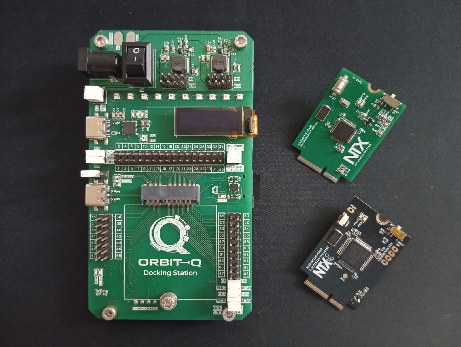
- Modular M.2 E-Key MCU architecture
- 75-position M.2 E-Key connector
- 6 V – 16.8 V DC input range
- 5 V @ 3 A and 3.3 V @ 3 A regulated power rails
- On-board STM32F103-based ST-LINK debugger
- CP2102 USB-to-UART bridge
- 128 × 32 monochrome OLED display
- 10 × WS2812B individually addressable RGB LEDs
- On-board microSD card interface
- 68 accessible I/O signals
- SPI, I²C, UART, PWM, ADC, USB and SWD interfaces
- Jumper-configurable peripheral connections
- Standard 2.54 mm expansion headers
Hardware Architecture
ORBIT-Q separates the microcontroller module from the main development platform.
The M.2 E-Key connector acts as the central interface between the installed microcontroller module and the board's power, communication, debugging, storage, display, and expansion subsystems. This allows compatible MCU modules to be changed while retaining the same development platform.
Power Management
ORBIT-Q uses two independent high-efficiency switching regulators to provide:
| Rail | Output | Maximum Current |
|---|---|---|
| 5 V | 5.0 V | 3 A |
| 3.3 V | 3.3 V | 3 A |
The board accepts power through either a DC barrel jack or dedicated battery input pads, with an operating input range of 6 V to 16.8 V. Dedicated power headers are also provided for external circuits and peripherals.
User Interfaces
OLED Display
ORBIT-Q includes an onboard 128 × 32 monochrome OLED connected through I²C.
It can be used for:
- System status
- Menus
- Sensor data
- Debug information
- User-defined graphics
A jumper-based interface allows the OLED connection to be isolated from the MCU module.
RGB LEDs
The board includes 10 WS2812B individually addressable RGB LEDs for:
- Visual feedback
- Status indication
- Diagnostics
- User applications
The LED interface uses a single-wire digital data connection with configurable power and signal routing.
USB-to-UART
A CP2102-GMR USB-to-UART bridge provides a USB serial interface between the host computer and the installed MCU module.
The interface supports:
- Firmware logging
- Serial communication
- Command-line interaction
- Debugging
Connection is provided through a USB Type-C connector.
M.2 E-Key Interface
The ORBIT-Q platform uses a 75-position M.2 E-Key connector as its primary microcontroller interface.
The connector provides access to:
- Power
- GPIO
- UART
- SPI
- I²C
- USB
- SWD
- Other MCU signals
The installed module acts as the central processing element for the onboard subsystems and expansion interfaces.
I/O Expansion
Three expansion headers provide access to 68 I/O signals from the installed microcontroller module.
Supported signals include:
- Digital GPIO
- UART
- SPI
- I²C
- PWM
- ADC
- USB
- SWD
- Power and Ground
The headers use standard 2.54 mm spacing for prototyping and external hardware connections.
MicroSD Card
ORBIT-Q includes an onboard microSD card interface using SPI.
It can be used for:
- Data logging
- Firmware storage
- Configuration files
- Removable storage
- Embedded application data
The interface is connected to the MCU module through dedicated SPI signals.
ST-LINK Debugger
An onboard STM32F103-based ST-LINK debugger provides programming and debugging for the installed MCU module through Serial Wire Debug (SWD).
The debugger uses a dedicated USB Type-C connector and operates independently from the USB-to-UART bridge and MCU USB interface.
Development
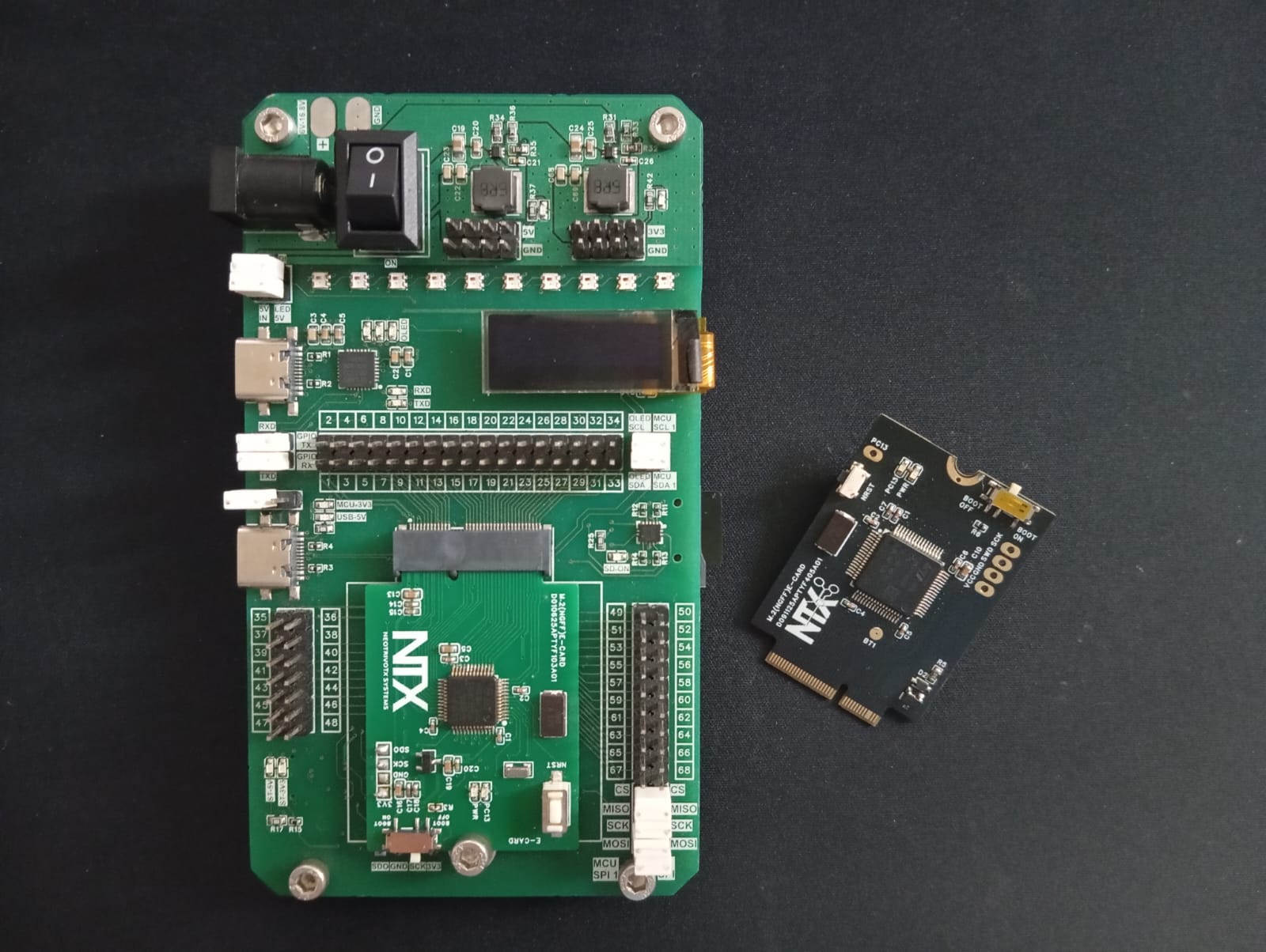
ORBIT-Q is designed for:
- Embedded software development
- Rapid prototyping
- Hardware validation
- Sensor and peripheral experimentation
- Data logging
- Custom embedded applications
The modular architecture allows developers to work with compatible MCU modules without redesigning the entire development platform.
Documentation
For detailed hardware information, pin assignments, jumper configurations, electrical specifications, and subsystem operation, see the ORBIT-Q Datasheet & Hardware Reference Manual.
Additional resources:
License
See the LICENSE file for details. All documentation, sample code, and software drivers in this repository are released under the MIT License. Hardware designs, layout files, and product specifications remain the proprietary IP of NTX Systems Pvt. Ltd.